One of the best decisions I made in college was to join the MIT FSAE Electric team, MIT Motorsports. The mission of the team was to design and build an electric racecar each year that would compete in the FSAE Electric competition, a college competition run by the Society of Automotive Engineers .
When I joined the team as a freshman it was only the second year after the team had switched from the gasoline powered racecar competition to the newer electric racecar competition. The switch was a daunting one, team already had a ton of knowledge about how to build a gasoline powered vehicle, but there was a huge number of new skills required to make a driving electric car, the previous year the team had not actually been able to complete a driving vechicle. Especially around the traction and battery systems. My freshman year there were also only a handful of EEs on the team.
My main project my freshman year was to create the vechicle dashboard. This was a controller mounted behind the steering wheel that took driver input to enable the vehicle. It also had LEDs to display several emergency indications to the driver. Best of all was a really loud and annoying buzzer that went off to indicate that the car was turned on.
My first iteration used a Arduino micro soldered to the board to control everything. Later versions would directly incorporate the ATMega328p processors typically on Arduinos to control the board. The microcontrollers were also connected to a CAN controller and transceiver chip that enabled the microcontroller to communicate with the rest of the vehicle electronics that was connected to the CAN bus, an electrical communication protocol designed for automobiles.
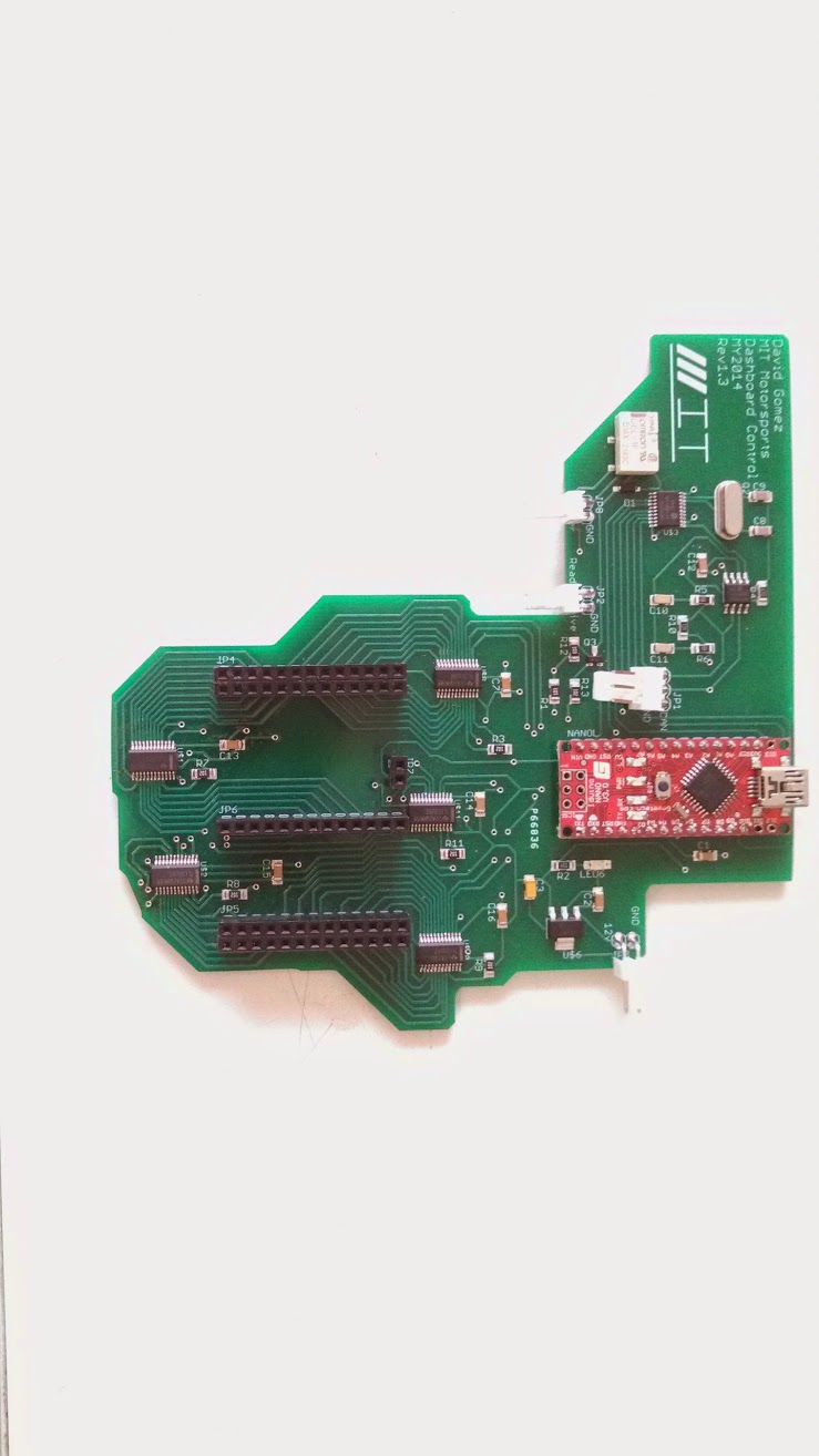
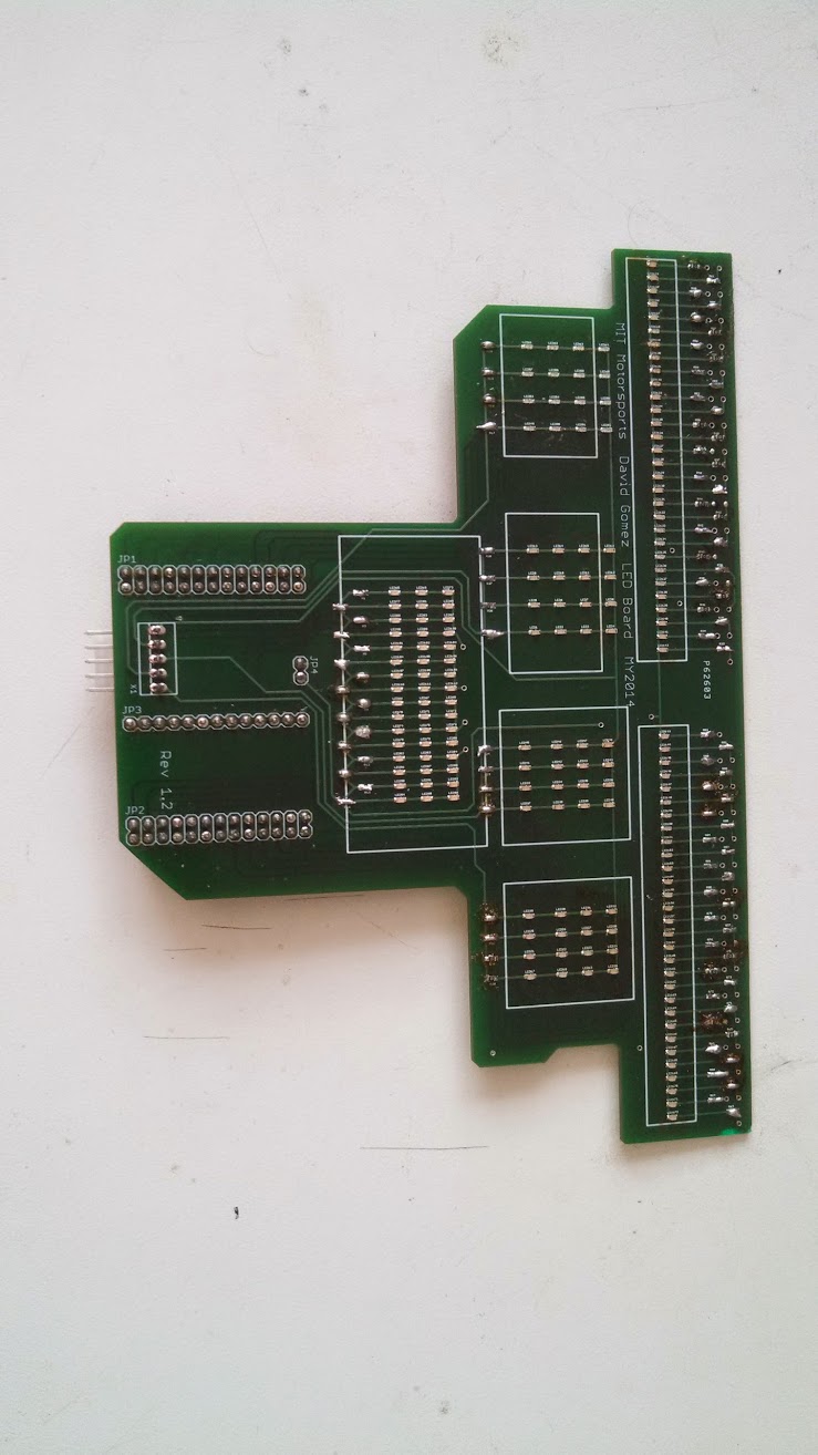
This first iteration of the board also used a double stacked design where the LEDs were all mounted onto a separate board that connected to the main board.
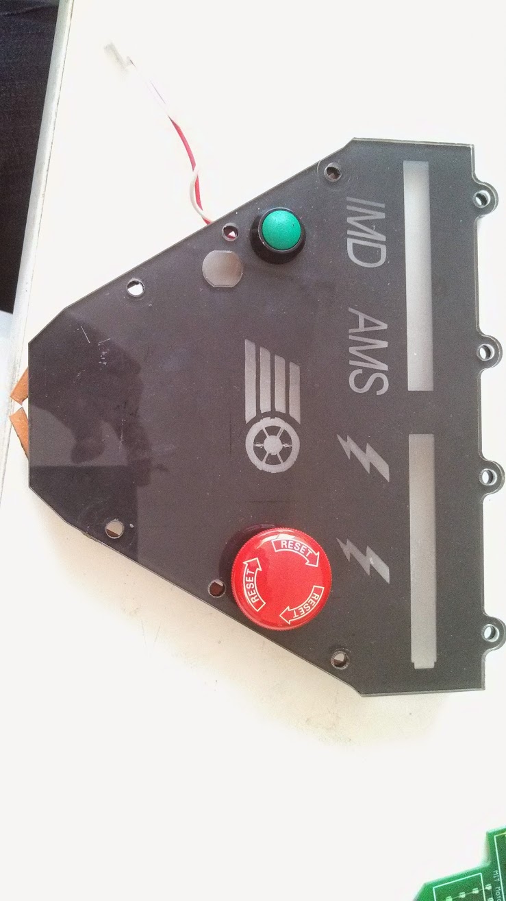
The whole PCB assembly went into box that mounted on the car. There was a front plate that mounted the buttons and also some light defusing logos for the indicators. Theres were made by painting the back of a piece of acrylic with high temperature barbecue paint and then rastering away the paint in the sections where logos are desired with a laser cutter.
My Sophomore and Junior years I worked on a variety of boards for the car and also was the team Low Voltage Systems lead. I coordinated and architected a lot of key low voltage sensor and control systems for the vehicle.
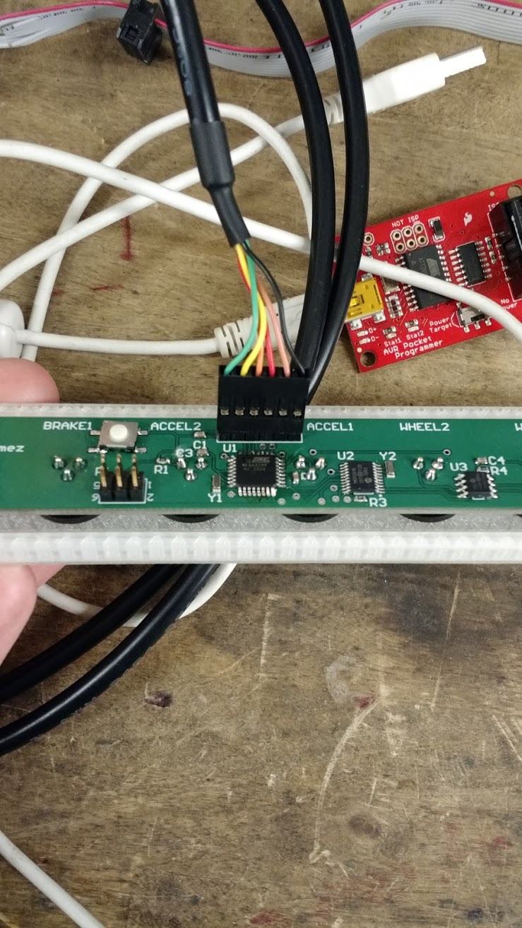
This is one of the boards I did that we called the CAN node, it connected to the accelerator pedals, brake pressure sensors, and some wheel speed sensors. All this information was fed to an ATMega328p that I implemented on the board. This microcontroller than dumped all the information from the sensors on the CAN bus.
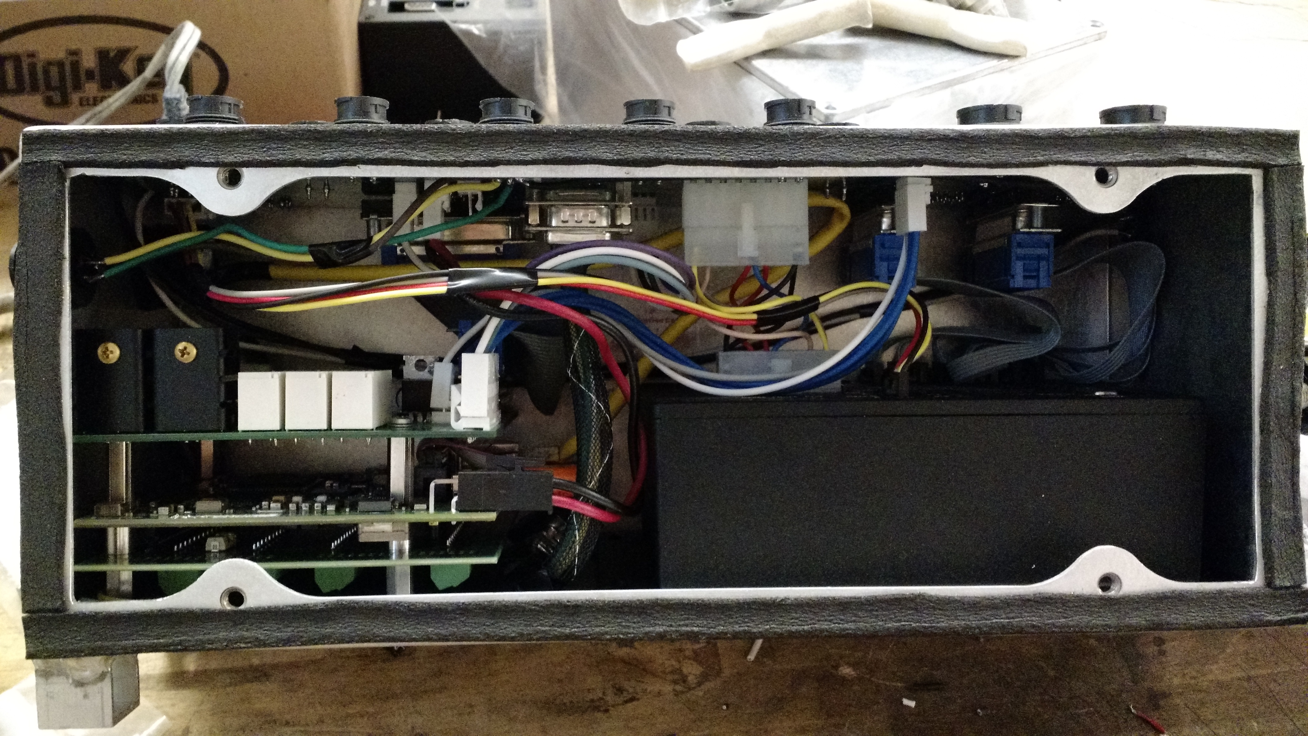
This box here is the Vehicle Control Unit. In the bottom left corner is the actual car computer, stacked on top of it is a safety shutdown board I worked on. This board had a bunch of analog circuitry that compared signals from all over the car and essentially turned it off if anything was off.
My senior year I worked on a wireless telemetry system to read information from the vehicle CAN Bus and stream it live to a computer on the side of the track that had custom python code I wrote to display real time graphs as well as log data. The electrical interface on the car that read information off the CAN bus also had a SD card so information could be safely logged on there as well. This is a short paper I did documenting the work.
UAP_Black_Box_David_Gomez